 Hotline:+8618073152920 Hotline:+8618073152920


— Blogs —
—Products—
 Consumer hotline +8618073152920
 WhatsApp:+8615367865107
Address:Room 102, District D, Houhu Industrial Park, Yuelu District, Changsha City, Hunan Province, China
Technical Support
Time:2022-01-01 19:07:32 Popularity:4150
Summary of RTU common problems RTU troubleshooting guide
4G RTU integrates traditional industrial RTU and full Netcom/4G/3G/5G data transmission functions into one, realizing comprehensive functions such as collection, counting, control, storage, alarm and transmission. It is also compatible with the data transmission function of the full Netcom/4G/3G/5G IP MODEM. Compared with purchasing collectors and DTU separately, it is cost-effective and effectively saves project investment. Today we will take a look at some common problems of RTU.

1, RTU power failure
The working indicator of a single power supply is off. Check whether the 220V AC input is normal. If it is normal, replace the power module. If there is no AC input or the voltage value is abnormal, replace the wiring from the MCB to the power module.
The two power module working indicators are off. Check whether the 220V AC input of the power module is normal. If it is normal, replace the power module. There is no AC input or the voltage value is abnormal. Check the wiring from the MCB to the power module. There is a virtual connection or short connection. If the situation occurs, replace it immediately. If there is no voltage at the circuit breaker, notify the water and electricity team to check the power supply from the distribution cabinet to the RTU.
2. RTU controller failure
1. The main CPU work indicator is not bright or has a fault code. If it is not automatically switched to the standby CPU, immediately manually switch to the standby CPU. Restore the factory default settings of the main CPU, re-download the program, and then dial the dial code back to the original position. After power-on, "BA" is displayed as normal, otherwise replace with a new CPU, configure and download the program;
2, the standby CPU work indicator is not on or displays a code other than "BA", follow the above steps;
3. The working indicator of the Ethernet port of the CPU is off. Check whether the two ends of the network cable are plugged in tightly. If they are plugged in tightly, contact the main control room to replace other Ethernet ports of the BB switch and execute the PING command on the CPU. PING works. Replace the BB switch, if PING fails, replace the CPU.
Three, RTU communication CPU failure
1. The communication CPU work indicator is off, check the wiring power supply, the wiring power supply is normal, replace the communication CPU;
2. The working indicator of the Ethernet port of the communication CPU is off. Check whether the two ends of the network cable are plugged in tightly. If they are plugged in tightly, contact the main control room to replace the other Ethernet ports of the BB switch and execute the PING command on the communication CPU. PING will work. , Replace the BB switch, if PING fails, replace the CPU.
Four, RTU redundancy switch module failure
The indicator of the redundant communication module is off. Contact the main control room to replace the redundant switching module. If it is still not normal, replace the backplane.
Five. IO board failure in RTU
1, the inspection found that the working light of a single IO board is off;
◆ If the meter connected to the card does not involve shutting in wells, contact the main control room and insert the card into the spare slot;
◆ If the instrument connected to the card involves shut-in, remove the RTU shut-in signal line, contact the main control room, insert the card into the spare slot, and restore the shut-in signal line after the card is normal;
2. The work light (green light) of all IO boards is found out during the inspection, and check whether the communication CPU is powered on;
◆ No power, power on the communication CPU, if the card is still not normal, replace the backplane;
◆ Powered on, replace the back panel;
3. The channel connected to the normal working instrument is red, disconnect the instrument loop, use the signal generator to simulate a 4-20mA current signal and send it to the card, and contact the main control room;
◆ The upper computer data display is not normal, then the channel is broken, replace the channel;
◆ The upper computer data display is normal and corresponds to the current value, then the cable from the clip channel to the meter terminal block is broken, and the wiring should be replaced immediately.
Prev:Classification of industrial routers
Next:How to prevent interference with 4G LTE wireless routers?
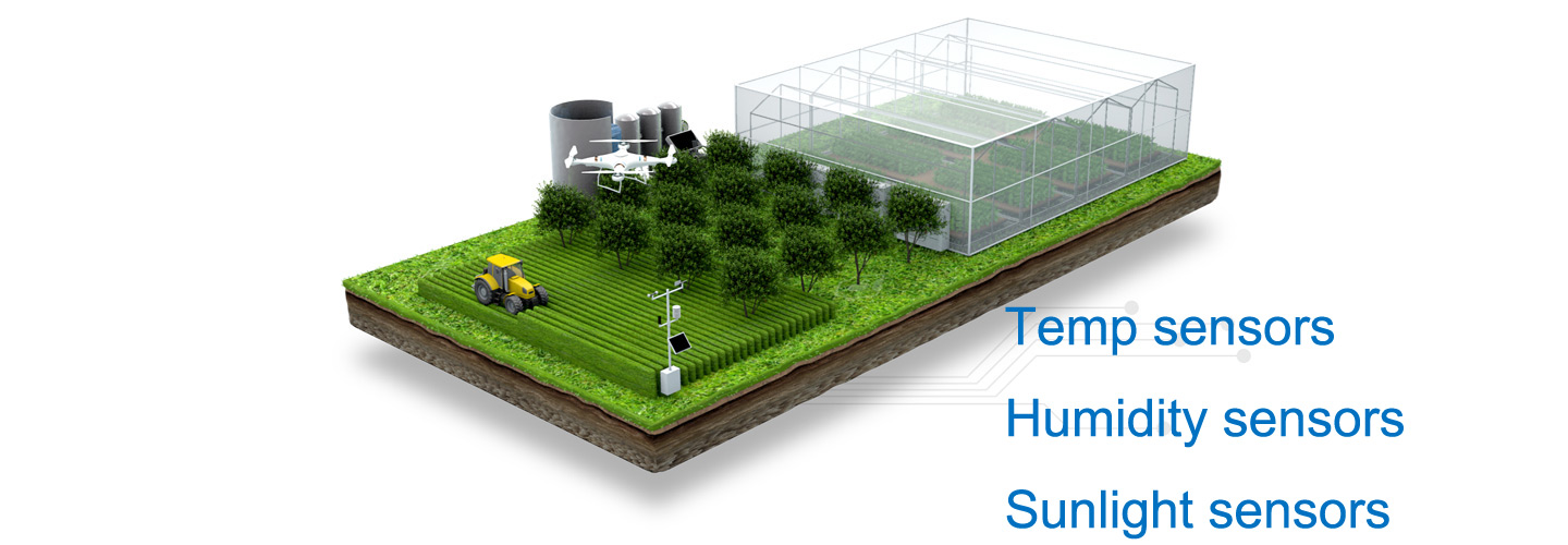
Sensors & Weather Stations Catalog
 Agriculture Sensors and Weather Stations Catalog-NiuBoL.pdf
 Weather Stations Catalog-NiuBoL.pdf
Agriculture Sensors Catalog-NiuBoL.pdf
Related recommendations
Related products
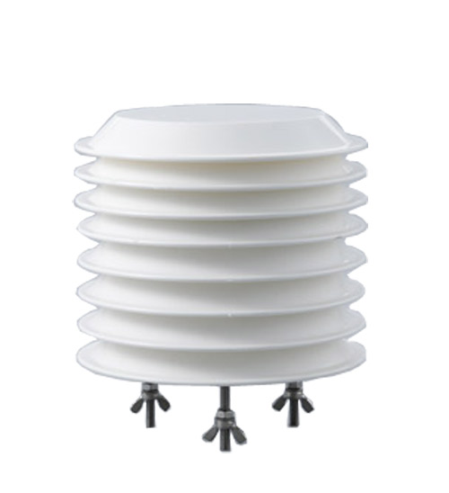 Atmospheric Temperature Humidity Pr···
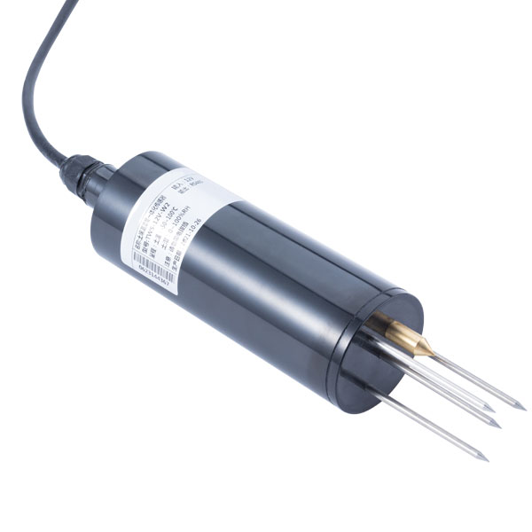 Soil Temperature Moisture Sensor 4-··· Air temperature, humidity and atmos···

Screenshot, WhatsApp to identify the QR code
WhatsApp number:+8615367865107
(Click on WhatsApp to copy and add friends)
